DigSigs in RFID
DigSigs on UHF RFID tags
In recent years UHF RFID tags have been gaining a lot of traction because of all the advantages they offer in tagging assets with data and protecting this data through built in mechanisms. This is especially true in the case the 2nd generation ISO/IEC 18000-63 tags which support on chip authentication and encryption using its TAM1 and TAM2 schemes respectively.
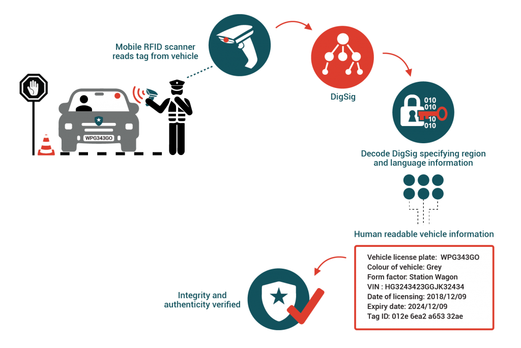
This article describes some of the problems with the TAM1 UHF RFID authentication scheme and how they can be solved using DigSigs. It also describes how a DigSig can be encoded into a RFID tag in a way so that a ISO/IEC 20248 aware RFID reader will know exactly what data needs to be read from which banks simply by performing a “inventory” over the tag and interpreting the results in accordance with the ISO/IEC 20248 specification.
This article assumes some background in understanding on the following topics
- Symmetric and asymmetric encryption schemes
- UHF RFID
DigSigs as standardised dynamic data structures for RFID
Background
It is widely understood that RFID tags can be used as lightweight data storage units. For simple applications a application designer might choose to simply store a database reference code in the tag. Other might choose to store some human readable ASCII encoded text; or a custom designed binary data structure. In all of these cases the reader of the tag needs to have a in depth understanding of the application.
Another problem that arises is that if the order of the fields need to change, or some data field needs to move from the EPC memory bank to the user memory bank then all readers and their relevant software modules will need to be updated to be able to interpret the new data structure.
Using Application Family Identifier to identify ISO/IEC 20248 tags
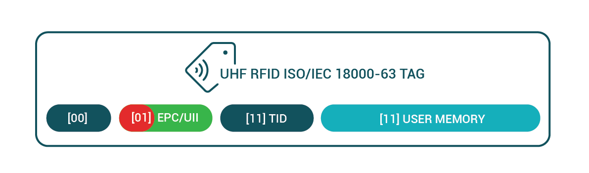
When a ISO/IEC 1800-63 tag becomes excited by a beam produced by a RFID reader the tag immediately starts emitting the data. The data emitted will be that which is contained in its UII/EPC memory bank. The first 16 bits of the data emitted is referred to as the “Protocol Control” or PC bits.
The PC bits structure describes various features of the tag. This includes things like the size of the UII/EPC bank, the mode of the tag, but also something referred to as the “Application Family Identifier” of the tag.
The Application family identifier, as defined in ISO/IEC 15961-3, is a 8 bit identifier that describes the type of data that the reader should be expecting on the tag. The ISO/IEC 20248 data structure has been registered with the relevant bodies and any reader detecting a tag with its AFI set to 0x92h should expect a DigSig data structure to be found inside the tag.
| ISO/IEC 2048 Application Family Identifier | 0x92h |
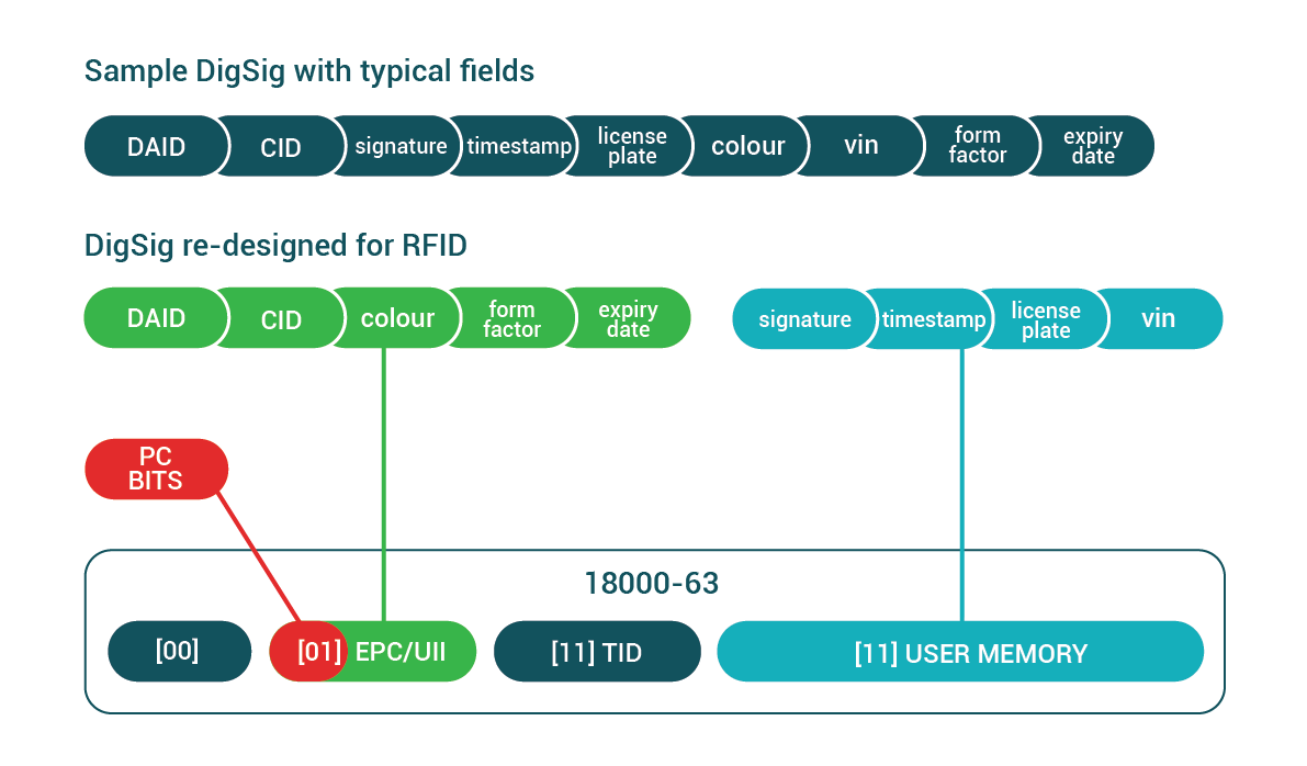
Breaking up a DigSig over multiple banks
DigSigs data structures can be broken up into several snips each of which can written into a different medium. This is extremely useful in the case of RFID because of the limited size of the UII/EPC databank.
Since the UII/EPC databank is usually limited to a size of between 96 bits and 128 bits there simply is not enough space to store cryptographic signatures. Even the smallest acceptable cryptographic signatures have a minimum size requirement of 384 bits.
The solution that DigSig specification suggests is that the DDD pragma features be used to break a DigSig up over multiple databanks.
- The first DigSig part, called the cidSnip must be stored in the UII/EPC bank of the RFID chip. This is because the DAID-CID snip is contained in this snip and it will be used by the reader to identify the data structure. Then that information can be used to know how to further interrogate the chip if needed.
- Other parts of the DigSig, such as the part that contain the signature field can be stored in the User Memory bank. The reader can be instructed on how to collect this data using the DDD pragma “readmethod” feature as described in the specification.
The diagram below shows how a DigSig might be broken up into multiple snips so that the data structure would be native to the RFID domain. This example also demonstrates how fields of immediate interest can be included to be part of the first snip so that this data can be collected as part of the inventory operation.
- Even if the rfid tag was only read partially then some fields will be available
- The reader only have to read the subset of data bank as specified in the DDD
What is “tag authentication”?
When you read data from a RFID tag, how can you know if the data read from this tag is authentic? meaning, how can you know if the data you read from a tag came from a trusted source? The process of determining the truth or legitimacy of a piece of data can be referred to as authentication.
The traditional way of solving this problem for RFID is by utilising the TAM 1 tag authentication features as described by ISO/IEC 18000-63. TAM 1 does this by sharing a secret 32 bit key with both the issuer of the data and the reader who wishes to verify the authenticity of the tag. To authenticate the tag the reader can then transmit a cryptographic “challenge” to the tag to which the tag can only correctly respond if it has the secret key stored on this chip itself.
The circuitry on passive RFID tags are designed to operate in low power conditions. This is because the physics of the solution dicates it. The amount of power that can be transmitted wirelessly to a tag using radio waves only is extremely limited. For this reason the processing power available on such a tag is extremely constrained. Even with these constraints the amount of processing that chip designers have been able to pump out of these chips is nothing short of amazing. And it is exactly these advances that have made it possible to perform AES encryption/decryption operations on the chip itself. Having symmetrical cryptographic functions on a RFID chip opened a whole new world of possibilities to the world of RFID. It was now possible to not only authenticate tags using AES challenges, but the over-the-air communication could now also be encrypted using the same circuitry.
Even with all of these advances in RFID technology; passive RFID tags are still a long way off from having enough processing power to utilise the power of asymmetric cryptographic such as RSA, ECDSA or ECBN.
The problem with TAM 1 authentication – the sharing and distribution of keys
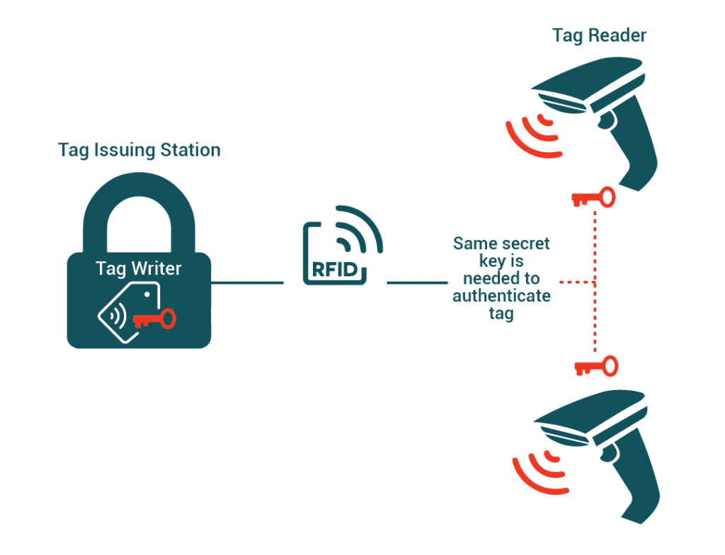
Symmetrical encryption algorithms have serious drawbacks; the biggest one being that both parties, the issuer and the reader/verifier needs to have access to the same secret encryption key.
The drawbacks of authenticating tags using TAM 1 AES as described in ISO/IEC 18000-63
- Secure key distribution is a technical challenge
- Should the key store of a single reader in the field become compromised then the integrity of all other tags using that key is also placed in jeopardy
Using DigSigs for authentication
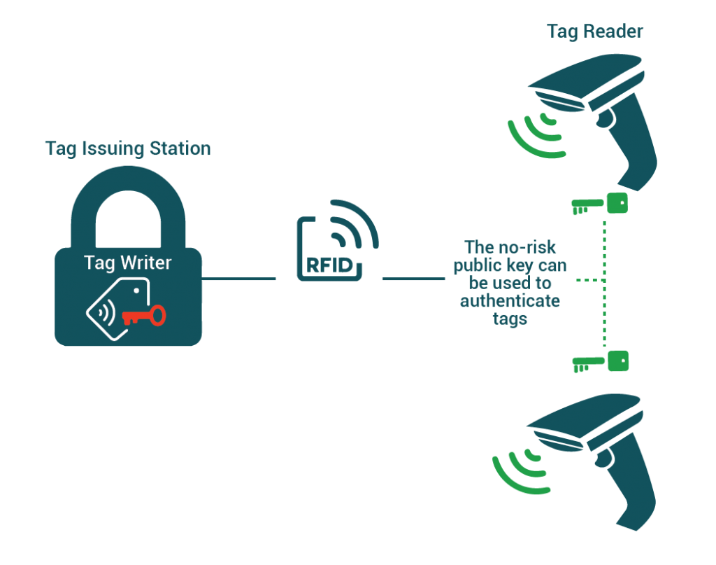
One of the standard DigSig fields is a “signature” field that was created during the DigSig creation process. Typically this signature would have been produced using a asymmetric elliptic curve encryption algorithm such as ECDSA or ECBN.
Asymmetric algorithms such as the ones mentioned above to not require a secret to be shared between the issuer and the reader/verifier. The reader/verifier only needs to have access to a X.509 DigSig Certificate which contains not only the instructions on how to decode the tag, the algorithm to verify signature but also the public key that can be used to validate a signature.
Using ISO/IEC DigSigs for tag authentication has the following advantages
- Public keys do not need to be kept secret because they cannot be used to produce signatures, they can only be used to verify them. This means that no secrets needs to be stored on the RFID reader thereby simplifying design and reducing risk.
- The contents of the TID (tag id) databank can also be signed into the DigSig signature field.